Flow Visualization/ANS 2026
The liquid that makes
a structure disappear
- Matching index of refraction (MIR)
- SLA 3D-printed test sections
- Particle image velocimetry (PIV)
A way to look only at the flow inside a complex 3D-printed reactor model, leaving the model itself right where it is. Match the refractive index of the fluid to that of the solid and light no longer bends at the boundary and the structure optically disappears.
 Sang Oh Shin
 Min Seop Song
01 — The problem
The more complex the geometry,
the less you can see
Next-generation reactors, among them very high temperature reactors, sodium-cooled fast reactors and molten salt reactors, have intricate internals. Pebble beds of spherical fuel, rod bundles wrapped in helical wire, helical coiled tubes: curved geometry is what sets the flow. Validating such a design means measuring the velocity field between those structures directly.
The trouble is light. Optical techniques such as PIV and LDV have the advantage of measuring without disturbing the flow, but light refracts at every solid–fluid boundary. On curved surfaces the effect is far worse: structures behind appear warped or disappear entirely, and you can no longer tell where you are measuring.
The fix is to remove the boundary itself. Match the refractive index of the fluid to that of the solid and light passes through without bending. That is matched index of refraction (MIR). Until now, though, the model had to be machined from acrylic (PMMA, about 1.49), and none of the geometries above can be machined.
Filmed in our laboratory · no sound
Video — Sangoh Shin
See it happen
A pebble bed disappears
A glass cell stands in front of a printed grid, and transparent pebbles, models of spherical fuel elements, are stacked one by one into the index-matched liquid to build a pebble bed.
Above the surface each pebble is plainly visible. The moment it sinks, it vanishes: solid and fluid share the same refractive index, so light no longer bends at the boundary and the grid behind shows straight through.
01.5 — The evidence
Five geometries vanish in the same liquid
Five 3D-printed test sections (a twisted prism, a pebble bed, wire-wrapped rods, a cylindrical tube and a gyroid) were each half-submerged in the same index-matched liquid, with a printed grid standing behind them.
Above the surface the structure distorts the grid. Below it the grid passes straight through. The geometry makes no difference.
Once the walls stop being visible, any plane inside can be picked and its velocity field measured.
What shows up once the wall is gone
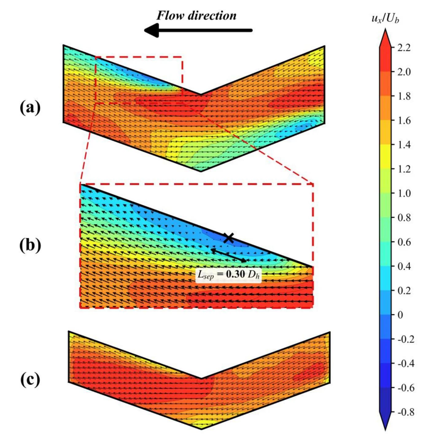
Time-mean velocity fields measured on two planes at different depths across one bend of a zigzag (PCHE) channel. With nothing obscuring the near-wall flow, the measurement reaches into the inner corner of the bend.
The mainstream follows the zigzag and reaches 2.0–2.2 times the bulk velocity. On plane (a) the core shifts towards the outer wall and a weak reversal appears just past the inner corner (minimum −0.13 Ub); (b) enlarges that spot, where the separated length is 0.30 hydraulic diameters.
On plane (c), at a different depth, the velocity is positive everywhere (minimum +0.9 Ub). The same bend behaves differently with depth.
02 — The model
If you cannot machine it, print it
Printing transparent resin on a stereolithography (SLA) printer removes the geometric constraint. None of the three models below could be made by conventional machining.
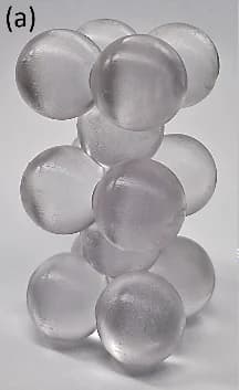
Pebble bed
페블베드
The core of a very high temperature reactor, packed with spherical fuel
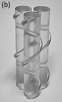
Wire-wrapped rods
와이어 랩 봉다발
Sodium-cooled fast reactor fuel rods wrapped in helical wire
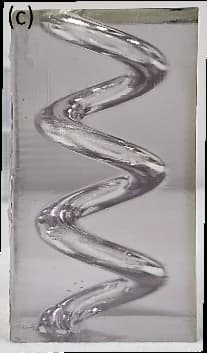
Helical coiled tube
나선형 전열관
Steam generator tubing for an integral reactor
Photographs — Sangoh Shin
The number to hit is 1.546
We measured the refractive index of the printed resin at four wavelengths with a prism coupler. It shows normal dispersion: the index falls as wavelength rises.
Printing at layer thicknesses of 0.05 mm and 0.025 mm gave almost the same values (1.544 and 1.546 at 532 nm). Print resolution therefore does not change the optical properties, so we took 1.546 at 532 nm, the wavelength PIV usually uses, as the target.
Because the whole 404 – 829 nm range was measured, the same fluid carries over to techniques using other light sources, such as PLIF.
Measured on the 0.025 mm layer specimen · prism coupler, TE mode, accuracy ±0.001
03 — The fluid
A liquid that is safe
and does not smell
Commercial SLA resins have refractive indices above 1.5. Every existing fluid in that range had a drawback. Aqueous sodium iodide corrodes metal and discolours; p-cymene is toxic and an irritant, and needs dedicated waste handling. An anise oil / mineral oil mixture proposed earlier smells too strongly to live with in a laboratory for long.
So we chose a base fluid with a high refractive index (1.567), low toxicity, and almost no odour: benzyl benzoate. To that we needed a co-solvent that would bring the index down to the target and lower the viscosity at the same time. There were three candidates, and the test was simple: does it mix?
- Base
Benzyl Benzoate
벤질 벤조에이트
- Index
- 1.567
- Viscosity
- 8.6 cP
- Density
- 1.118 g/cm³
The question is what to mix into this fluid.
Mineral Oil
광유
- Index
- 1.459
- Viscosity
- 70 cP
- Density
- 0.85 g/cm³
✕The phases separate and the mixture turns cloudy. Unusable for optical measurement.
Silicone Oil
실리콘 오일
- Index
- 1.405
- Viscosity
- 970 cP
- Density
- 0.97 g/cm³
✕The phases separate and the mixture turns cloudy. Unusable for optical measurement.
IPM
이소프로필 미리스테이트
- Index
- 1.435
- Viscosity
- 4.7 cP
- Density
- 0.85 g/cm³
○Mixes completely into a clear solution. Its low viscosity and density also help in controlling the flow.
Mineral oil and silicone oil would not mix with benzyl benzoate. Only isopropyl myristate was fully miscible, giving a pair whose ratio alone sets both the refractive index and the viscosity.
04 — Try it yourself
Change the ratio and the temperature
Every value below is computed live from the correlations in the paper. The closer you get to the target index of 1.546, the straighter the grid on the left becomes, and at an exact match the structure disappears.
Mixture index
1.5459
Offset from target
−0.0001
Viscosity
7.5cP
This is the optimum composition at this temperature (φ = 0.841)
The refractive index is computed from the Arago-Biot mixing rule with a thermo-optic coefficient; the viscosity from the Grunberg-Nissan and Arrhenius equations. The temperature correlation was measured at φ = 0.8, and the viscosity-temperature plot uses that same composition.
05 — Validation
It really does disappear
A twisted prism was immersed in three different media and photographed against a 1 cm background grid. Having both curvature and twist at once, it is a demanding test of how well index matching works.
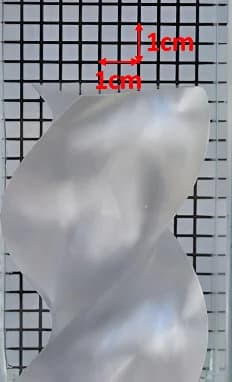
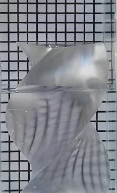
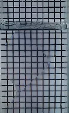
Twisted prism model · 1 cm background grid
Photographs — Sangoh Shin
- Medium index
- 1.546
- Offset from model
- +0.000
The model is barely visible and the grid runs straight through it. Light does not bend at the boundary.
06 — Takeaways
What this makes possible
The geometric constraint is gone
Pebble beds, wire-wrapped bundles, and helical coiled tubes that could not be machined can now be printed and tested as they are.
It is safe and easy to handle
Neither corrosive nor toxic, and almost odourless. It can stay in routine laboratory use without special waste handling.
The design values can be computed
At a volume fraction of 0.84, the index is 1.546 and the viscosity about 7.5 cP. Because the variation with composition and temperature is captured in correlations, the working point can be computed in advance for any test condition.
Next steps
Validation with a real PIV system and PLIF particles, and a quantitative assessment of the measurement error caused by an index mismatch.
Source
Sangoh Shin, Min Seop Song, “Experimental Validation of a Novel Refractive Index Matching Technique Using SLA 3D-Printed Models for Optical Flow Measurements in Nuclear Thermal-hydraulic Experiments,” American Nuclear Society, 2026.
This work was supported by the Korea Institute of Energy Technology Evaluation and Planning (KETEP) and the Ministry of Climate, Energy and Environment (No. RS-2024-00398867), and by the Innovative SMR Technology Development Agency (No. RS-2024-00404240).